Essential Tips for Safely Adding an Extension to Your Building
- truenotesrakesh
- Feb 14
- 7 min read
How to Safely Add an Extens Author: Rakesh kumar
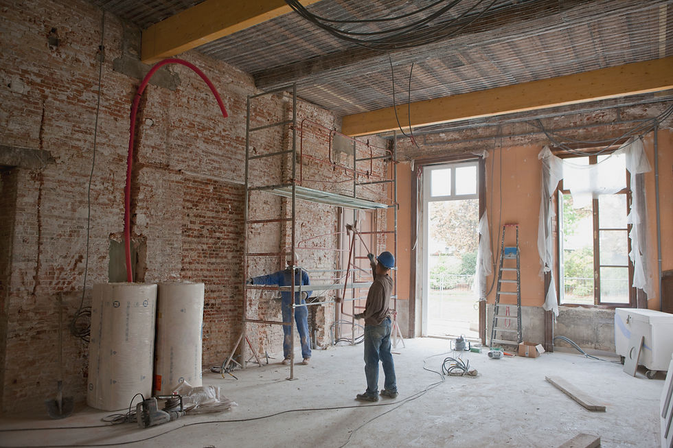
Adding an extra floor or extending your building is a great way to maximize space and increase property value. However, before you start construction, it’s essential to ensure that the existing structure—including floors, beams, columns, reinforcement, and load-bearing walls—can safely support the additional weight.
This is especially challenging if the original building drawings are unavailable. In such cases, Non-Destructive Testing (NDT) methods are crucial for assessing the structural capacity without causing any damage.
This comprehensive guide covers:
Assessing Structural Capacity Using NDT Methods – Check the strength and integrity of structural elements.
Structural Analysis and Design – Calculating and designing the structure to safely support new loads.
Architectural Review – Ensuring the new extension complements the existing design and complies with building regulations.
Reinforcement Methods – Strengthening weak elements before construction.
Construction Procedures – Safe practices for adding additional floors without compromising structural integrity.
This guide uses simple language to help you safely and effectively extend your building.
1. Why Check Structural Capacity Before Adding an Extension?
Adding an extension increases the weight on the existing structure. If the floors, beams, columns, reinforcement, or load-bearing walls aren’t strong enough, it could lead to:
Cracks in walls, ceilings, and floors
Uneven or sagging floors
Structural failure, risking safety and expensive repairs
Non-Destructive Testing (NDT) methods are ideal for evaluating the structural capacity without causing damage. This is particularly useful when:
Original Drawings Are Unavailable – NDT methods help you understand the structural layout and design details.
Structural Integrity Needs Verification – To ensure the building can safely support additional loads.
Preserving the Building is Essential – Ideal for heritage structures or buildings in continuous use.
2. Preliminary Checks
2.1 Review Building Documents
What to Do: Gather the original building plans, structural drawings, and design calculations (if available).
Why It Matters: This helps you understand the building’s original design load, materials used, and structural layout.
2.2 Visual Inspection
What to Look For:
Cracks or Sagging: Indicate overloading or weakening.
Rust or Corrosion: Especially on steel reinforcement or beams.
Water Damage: Can weaken concrete, steel, or timber.
Why It Matters: These signs indicate existing structural issues that must be addressed before adding more weight.
2.3 Building History and Site Survey
What to Do: Interview building owners or occupants to understand:
Any modifications or extensions previously made.
History of repairs or structural issues.
Site Survey: Measure building dimensions and heights to recreate a structural layout.
2.4 Reconstructing Structural Drawings
What to Do: Use NDT results to create as-built structural drawings.
Why It Matters: Helps in load calculations and structural analysis for the extension.
3. Architectural Review
3.1 Design Compatibility
What to Do: Ensure the new extension complements the existing architectural style.
Considerations:
Aesthetics: Harmonize materials, colors, and shapes with the existing building.
Functionality: Plan room layouts that integrate smoothly with the existing spaces.
Access and Circulation: Design proper access points like staircases or elevators for the new floors.
3.2 Building Regulations and Zoning Laws
What to Do: Check local building codes and zoning regulations for height limits, setbacks, and floor area ratios.
Why It Matters: Ensures compliance with legal requirements to avoid penalties or demolition orders.
3.3 Natural Light and Ventilation
What to Consider: Ensure that the extension doesn’t block natural light or airflow to existing rooms.
Solutions: Use skylights, larger windows, or open floor plans to maintain light and ventilation.
4. Structural Analysis and Design
4.1 Load Calculation
What to Do: Calculate the new loads that the extension will add to the existing structure, including:
Dead Load: Weight of new walls, floors, and roofing materials.
Live Load: Weight of furniture, people, and other movable items.
Wind Load and Seismic Load: Environmental forces acting on the building.
4.2 Structural Analysis
Methods Used:
Finite Element Analysis (FEA): Computer simulations to check how the structure responds to the new loads.
Manual Calculations: For smaller projects, manual calculations can be done for simpler load distribution checks.
4.3 Structural Design and Detailing
For RCC Buildings:
Beam and Column Design: Calculate dimensions and reinforcement needed to support the new loads.
Slab Design: Ensure the existing slab can support additional floors.
Shear Wall Design: To resist lateral loads from wind or earthquakes.
For Steel Buildings:
Beam and Column Design: Check the adequacy of existing steel sections or add new ones.
Connection Detailing: Design strong connections using bolts, welding, or plates to safely transfer loads.
Bracing Design: Add diagonal bracing to resist lateral forces.
5. NDT Methods for Assessing Structural Capacity
5.1 Floors, Beams, and Columns
Rebound Hammer Test:
Purpose: Estimate surface hardness and compressive strength of concrete.
Procedure:
Clean the surface to remove dust or loose particles.
Hold the rebound hammer perpendicular to the surface.
Press the hammer until it impacts and records a rebound value.
Repeat at least 6 times at different points and take the average.
Expected Results: Higher rebound values indicate higher compressive strength.
Next Steps: If values are below design requirements, consider strengthening methods like jacketing or carbon fiber wrapping.
Ultrasonic Pulse Velocity (UPV) Test:
Purpose: Detect internal cracks or voids.
Procedure:
Apply coupling gel on the surface to enhance signal transmission.
Place the transmitter and receiver probes on opposite sides.
Measure the time taken for ultrasonic waves to travel through the concrete.
Expected Results: Lower velocity indicates cracks or voids.
Next Steps: If significant defects are detected, plan for repairs or reinforcement.
5.1 Floors, Beams, and Columns (Continued)
Ground Penetrating Radar (GPR):
Purpose: Locate reinforcement bars, check spacing, and detect voids.
Procedure:
Scan the surface using a GPR device by moving it evenly across the area.
The device sends electromagnetic waves that reflect back from objects like rebar or voids.
Analyze the reflected signals on the screen, which show the position and depth of embedded elements.
Expected Results: Clear patterns indicate reinforcement bars and their spacing. Irregularities may suggest voids.
Next Steps: If reinforcement is insufficient, consider additional reinforcement or structural strengthening.
Half-Cell Potential Test:
Purpose: Measure the corrosion risk of steel reinforcement in concrete.
Procedure:
Expose the rebar by removing a small portion of concrete cover.
Connect the reference electrode to the exposed rebar.
Measure the electrical potential difference across the surface.
Expected Results:
Low corrosion risk, Moderate corrosion risk, High corrosion risk.
Next Steps: If corrosion risk is high, consider cathodic protection or rebar replacement.
5.2 Load-Bearing Walls
Schmidt Hammer Test:
Purpose: Check the compressive strength of masonry walls.
Procedure:
Clean the masonry surface.
Press the Schmidt hammer perpendicular to the surface and trigger the impact.
Record the rebound value.
Repeat at least 6 times at different points and calculate the average.
Expected Results: Higher rebound values indicate higher compressive strength.
Next Steps: If the wall strength is inadequate, consider reinforcement with steel plates or jacketing.
Flatjack Test:
Purpose: Measure in-situ stress and strain to assess wall stability.
Procedure:
Cut a thin horizontal slot in the mortar joint.
Insert a flat hydraulic jack into the slot.
Pressurize the jack and measure the deformation.
Calculate the in-situ stress and modulus of elasticity.
Expected Results: Low stress values indicate weakened walls.
Next Steps: If stability is compromised, use external bracing or wall grouting.
Crack Monitoring:
Purpose: Observe the movement and propagation of cracks over time.
Procedure:
Attach crack monitoring gauges across visible cracks.
Record the initial width of the crack.
Monitor and record the crack width periodically (e.g., weekly or monthly).
Expected Results:
Stable crack width: No immediate action needed.
Expanding crack width: Structural weakness or ongoing movement.
Next Steps: Reinforce with steel bracing or carbon fiber wrapping if cracks continue to grow.
6. Foundation Testing and Capacity Check
6.1 Plate Load Test
Purpose: Determine the bearing capacity and settlement characteristics of the foundation soil.
Procedure:
Clear and level the test area on the foundation.
Place a steel plate on the foundation surface.
Apply incremental loads using hydraulic jacks.
Measure the settlement for each load increment using dial gauges.
Continue until the settlement becomes constant or failure occurs.
Expected Results: The load-settlement curve helps estimate bearing capacity.
Next Steps: If the bearing capacity is insufficient, consider soil stabilization or foundation underpinning.
6.2 Electrical Resistivity Test
Purpose: Assess soil moisture content and detect underground voids or weak zones.
Procedure:
Insert four electrodes into the soil at equal distances.
Pass a current through the outer electrodes and measure the potential difference between the inner electrodes.
Calculate the soil resistivity.
Expected Results:
High resistivity: Dry or compact soil with good bearing capacity.
Low resistivity: High moisture content or voids indicating weak zones.
Next Steps: If weak zones are detected, soil improvement or grouting may be required.
7. Strengthening Techniques
7.1 Carbon Fiber Wrapping
Purpose: Increase load capacity without adding much weight.
Procedure:
Clean the surface and remove loose particles.
Apply an epoxy primer.
Wrap carbon fiber sheets around beams, columns, or walls.
Apply a protective topcoat to shield against environmental damage.
When to Use: For enhancing flexural and shear capacity of beams and columns.
7.2 Steel Plate Bonding
Purpose: Enhance strength by gluing steel plates to concrete elements.
Procedure:
Clean and roughen the concrete surface.
Apply a high-strength epoxy adhesive.
Fix the steel plates using temporary clamps.
Allow the adhesive to cure before loading the structure.
When to Use: To increase load capacity of beams and slabs.
7.3 Jacketing
Purpose: Provide additional support and increase cross-sectional area.
Procedure:
Remove plaster and expose the reinforcement.
Add new reinforcement bars as required.
Formwork is placed around the element.
Pour concrete to form a jacket around the column or beam.
When to Use: For heavily loaded columns or when seismic strengthening is needed.
8. Construction Procedures
Material Selection: Use lightweight materials to minimize additional load.
Temporary Support: Install temporary shoring to prevent stress during construction.
Sequence of Construction:
Strengthen foundations and columns first.
Build new beams and floors sequentially.
Ensure each level is adequately supported before moving to the next.
9. Conclusion
Adding an extension requires thorough testing using NDT methods, structural analysis, and architectural review. This ensures the safety and durability of the new extension. Reinforce weak elements before construction to prevent damage or structural failure.
By following these detailed testing procedures and taking the right actions based on the results, you can safely extend your building while maintaining structural integrity. Always consult with qualified structural engineers and architects and follow local building codes for a safe and successful project.

Hozzászólások